The active thermal probe
Scope of delivery, variants
System diagram for version with external control unit

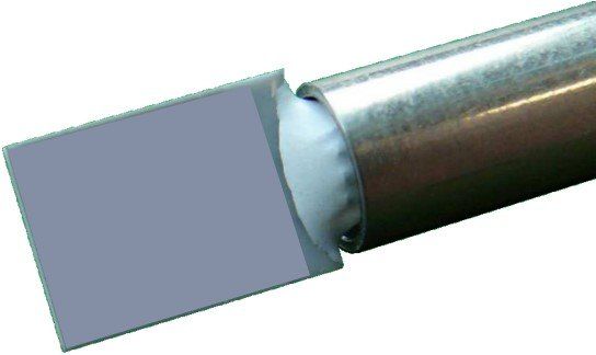
Probe with sensor and connector
- Metallized sensor surface to which a bias voltage of up to 500 V can be connected via the control unit
- Delivery also with double probe for direction-dependent measurement of the energy influx (this includes completely different system components)
- Length of the probe shaft from 5 to 50 cm, depending on customer requirements
- special connector for connection to the probe cable
probe cable
- vacuum-compatible connection cable between probe and vacuum feedthrough
- Sheathing made of durable stainless steel mesh
- Cable length from 0.2 m to 4 m, according to customer's requirement
- special probe-side connector
- LEMO connector as a connector to the vacuum feedthrough. When using other feedthrough plug type according to customer requirements
vacuum feedthrough
- A LEMO vacuum feedthrough mounted on a blind flange KF40 is supplied as standard
- other feedthroughs on request
- Can also be mounted on other sizes and types of feedthroughs, such as ISOK or CF
- Use of other types of feedthroughs on request
Connection cable to the control unit
- multi-pole connection cable between the vacuum feedthrough and the control unit
- Length from 1.5 m to 12 m according to customer's requirement
- equipped with LEMO connectors as standard, also with other suitable types of connectors on the probe side depending on the type of feedthrough
External control unit
- Serves to provide the supply voltage for the probe, its control, the temperature regulation as well as the recording and processing of the measured values
- The measured values are transmitted to the computer and control commands are received via a USB interface.
- Set parameters for the measurement regime and temperature control are saved and retained after switching off
Basic software for operation with an external control unit
- Configuration of the measurement process, such as the sampling rate of the measured values, coefficients of the temperature control and the target temperature of the probe
- continuous display of the measured values in a simple diagram
- Storage of the readings of temperature and heating power of the probe in a text file in tabular form
Internal control unit (optional)
- Converter card integrated in the computer for transmitting the control signals and receiving the measured values
- For this purpose, an externally connected signal adjustment is supplied, which is connected to the converter card with a special cable
- All tasks of control, regulation, recording of measured values and processing of measured values are taken over by a special software installed in the computer.
- This embodiment variant is particularly interesting for R&D issues, as it allows more degrees of freedom for the design of the measurement process and the processing of the measured values.
- But also for industrial applications to enable integration into existing plant systems
Analysesoftware „curve“ (optional)
- Graphic visualization of functions from tables of values saved with the control software of the probe as well as in any format
- Convenient interactive variation of the graphical representation with a simple mouse click (zoom, move, smooth, fit, etc.)
- Section-by-section fitting of the measured values and analysis of level differences of the course of the heating power of the sensor to neighboring sections
- Automatic compensation of measured value drifts caused by external heat sources.
- Determination of the functional equation of drifts
- Automatic determination of the energy values of any length of measurement series, taking into account the drifts and control oscillations that have occurred
- Output of the calculated energy influxes in tabular form
- Reduction of the time required to up to 1/100 compared to the determination of measured values with other systems
- No control of the probe or recording of measured values online
Software for variant with an internal converter card (optional)
- Configuration of the measurement process, such as the sampling rate of the measured values, coefficients of the temperature control and the target temperature of the probe.
- Specification of threshold values for the energy influx. If exceeded, a warning signal can be passed on to an external device or a message via the network.
- Monitoring of the time course of the heating power of the probe with regard to the measured value scatter (caused, for example, by interference signals) and their drift
- Variable specification for the maximum values of current, voltage and heating power to protect the probe
- Transmission of a message in the event of a probe failure
- Remote control of the software from a host computer on a network (LAN, protocol: TCPIP)
- All functions of the "curve" software are integrated in this software!
- Even when the measurement is running, the energy input can be calculated according to these modules without disturbing the recording of the measured values.
- Extensive service modules integrated, such as measuring the resistance of the supply lines, calculating the amplification factors for the signal converter, testing the controller system, etc.


